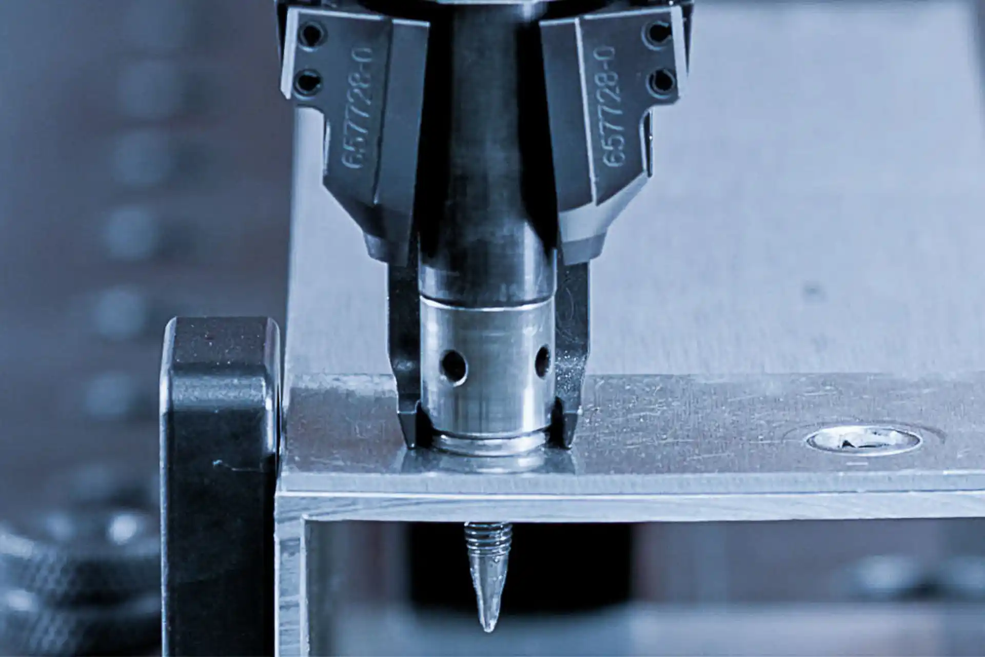
Flow drilling screwdriving is a joining process in which a special screw is inserted directly into metallic materials without pre-drilling. The combination of axial pressure and high rotational speed generates frictional heat that plasticizes the material. The screw penetrates the material, forming a flow hole and a metric thread, resulting in a high-strength, detachable joint.
WEBER-Technology
What you should know about flow drilling screwdriving
What flow drilling screwdriving means
Flow drilling screwdriving is used wherever different materials, one-sided accessibility, and high process reliability are required.
Areas of application for flow drilling screwdriving

Automotive and e-mobility industry
For body components, battery housings, and high-voltage components, flow drilling screwdriving is the preferred joining technology.
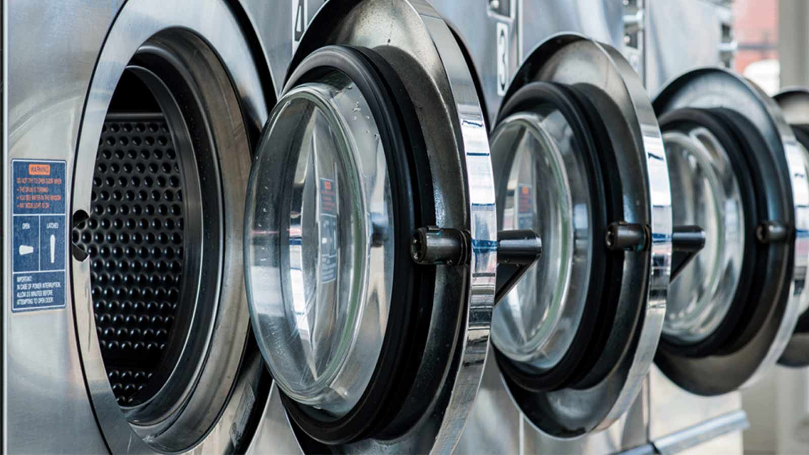
Household appliance industry
Ideal for stable, durable screw connections with varying sheet thicknesses and material combinations.
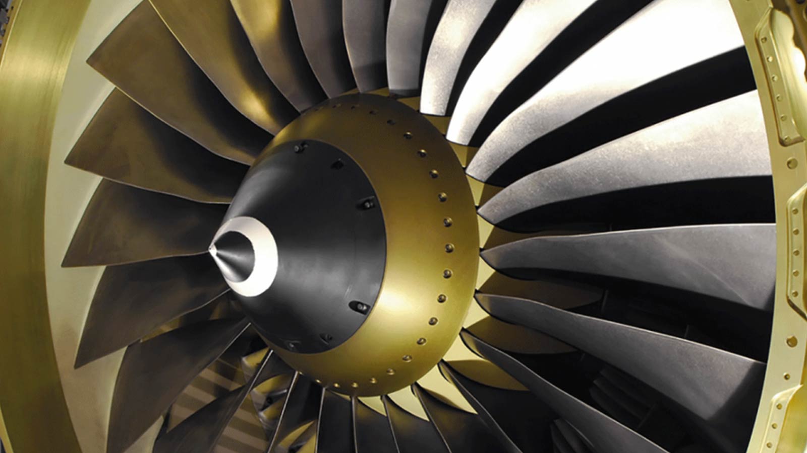
Aerospace industry
Lightweight construction particularly benefits from this one-sided, chipless joining process.
Mechanical engineering
When precise, detachable joints with high load capacity are required.
Process sequence of flow drilling screwdriving
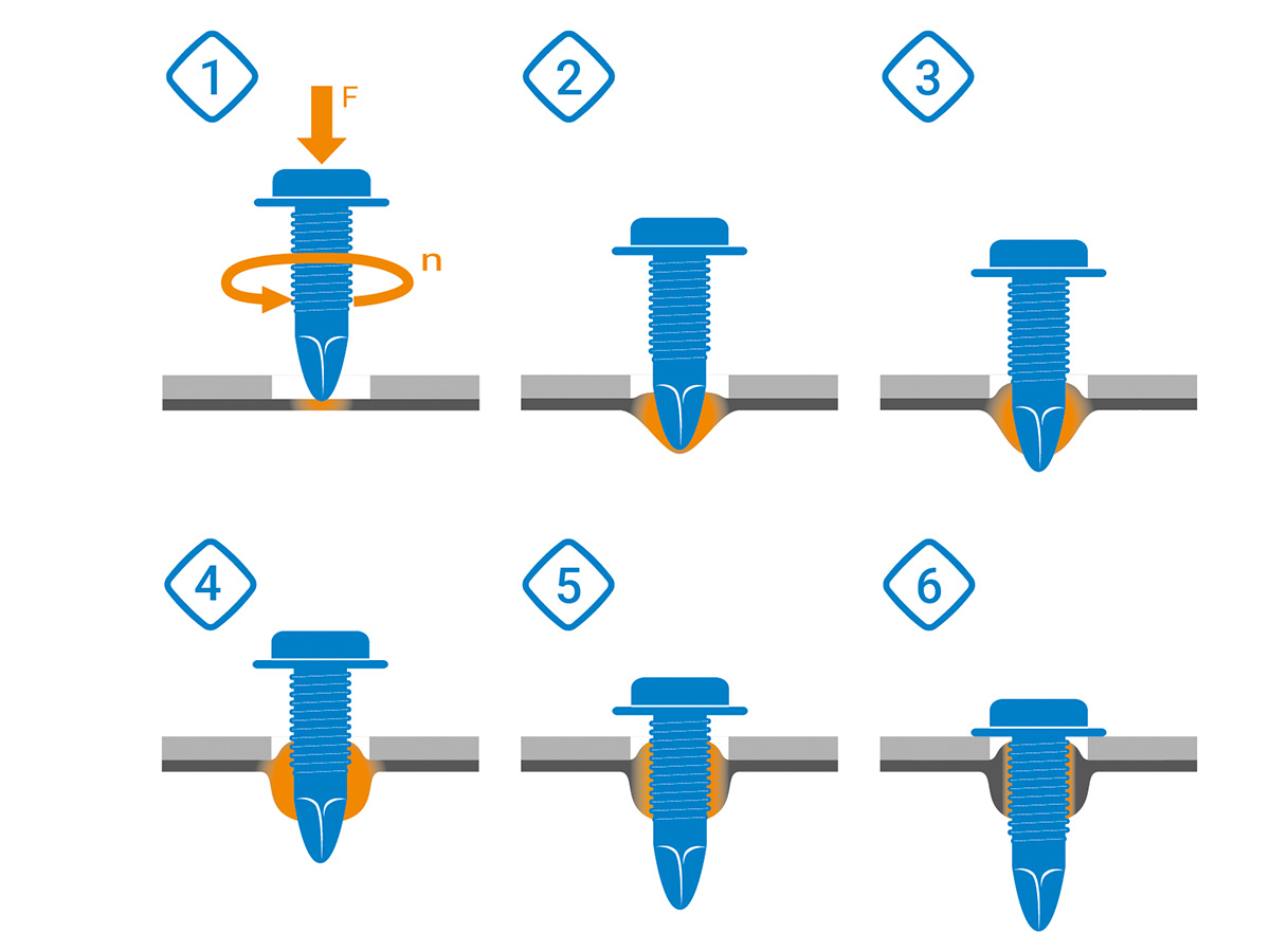
Phase 1: Frictional heating
The sheet is heated by the combination of contact force and high rotational speed. The friction generates sufficient heat to plastically deform the material.
Phase 2: Material penetration
The conically shaped screw tip penetrates the softened metal and begins forming a flow hole — entirely without pre-drilling.
Phase 3: Formation of the bushing
As the screw continues to penetrate, a cylindrical bushing is formed in the material, creating the basis for subsequent thread formation.
Phase 4: Thread forming
In the next step, a metric, gauge-compliant internal thread is formed directly in the component through chipless thread forming.
Phase 5: Screw insertion
The screw is fully driven through the formed thread.
Phase 6: Anziehen auf Drehmoment
Finally, the screw is tightened with the defined torque, creating a high-strength, detachable joint.
Advantages of WEBER technology in flow drilling
WEBER relies on several patented functions in flow drilling screwdriving that make the process significantly more efficient and robust.
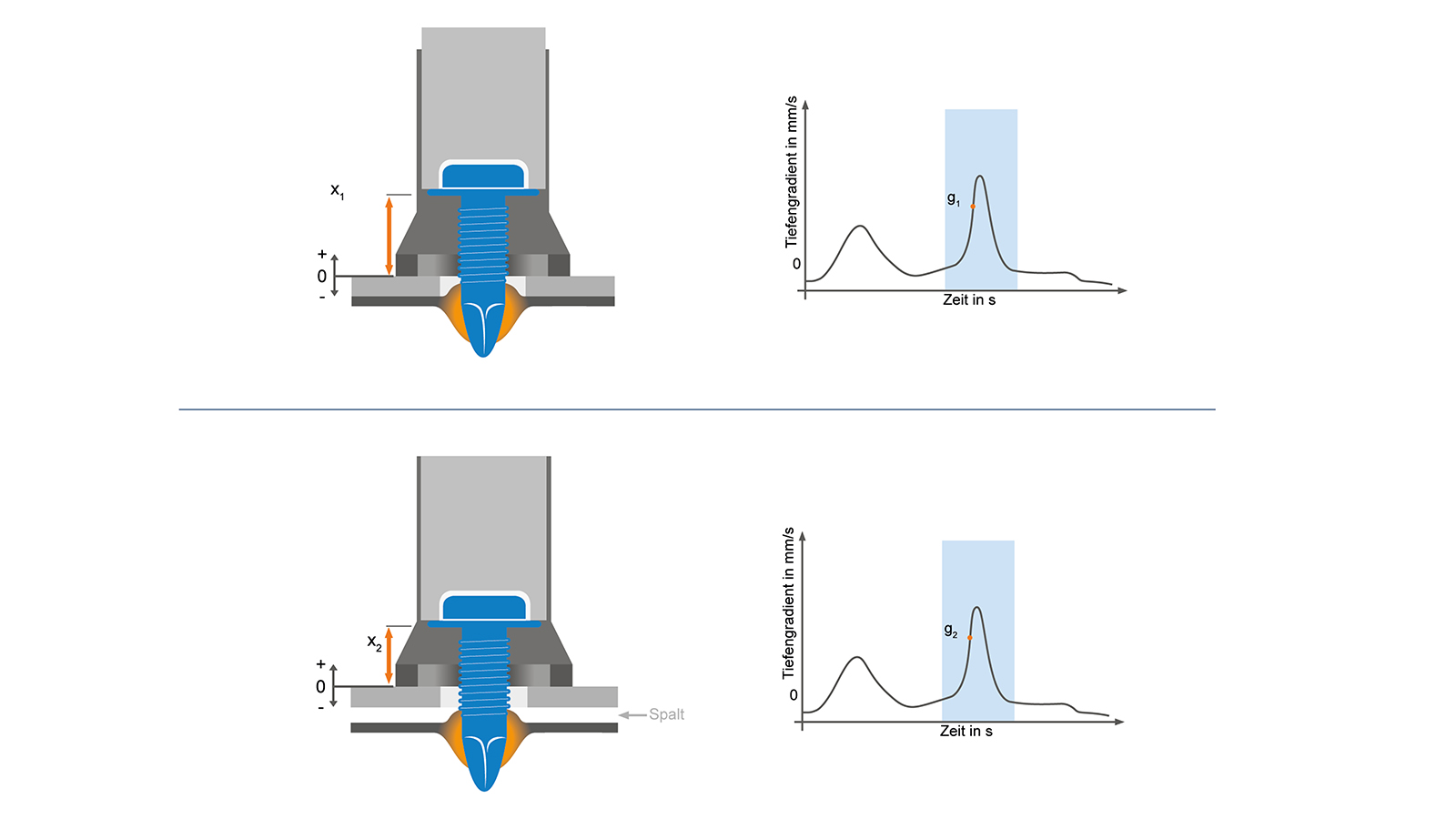
Patented WEBER depth gradient:
For process-reliable screwdriving, the optimal coordination of force and rotational speed is crucial: high values are required during flow drilling, while lower forces are needed during subsequent thread forming. Thanks to the patented WEBER depth gradient, the system automatically detects the material breakthrough and precisely switches between the processing phases—regardless of material thickness or component gaps.
As shown in the diagram, the gap between the materials to be joined causes the distance x₁ to differ from x₂. Nevertheless, in the screwdriving curve, g₁ = g₂ remains constant.
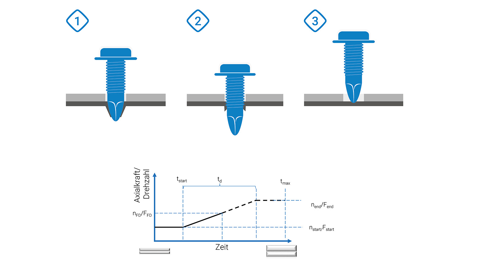
Patented WEBER Boost function:
Fluctuations in material strength and thickness can cause parameter sets defined in the laboratory to no longer function optimally in production practice. Up to now, readjustment has been a very time-consuming process that must be repeatedly adapted to the current production conditions. To solve this problem, the C50S controller uses the Boost function of the RSF25: it automatically increases both axial force and rotational speed until the depth gradient is reached.
The diagram shows three screwdriving cases: screw 1 with material at nominal thickness, screw 2 with material at the lower tolerance limit, and screw 3 with material at the upper tolerance limit.
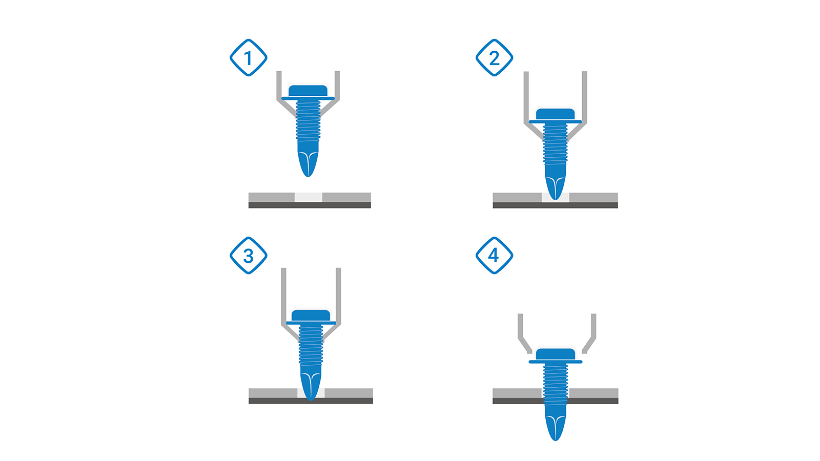
Automatic pilot hole compensation:
The screw is guided by the jaws until the screw tip and shank have penetrated the material, regardless of the pilot hole depth. The jaws then open, and the screwdriving process can begin.
The advantages:
- Simplified spare parts management through standardized variants
- Increased process availability
- Reduced NIO rate (non-OK parts)
- Reduced wear
The diagram shows how the screwdriver first approaches the sheet (1). The jaws remain closed (2). Then the screw tip penetrates the material (3). Only then do the jaws open (4).
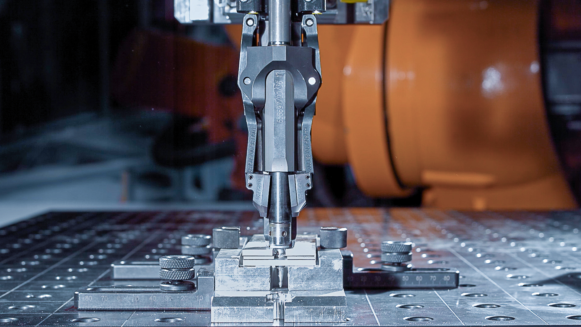
Structure of the WEBER RSF screwdriving system
You are currently viewing a placeholder content from YouTube. To access the actual content, click the button below. Please note that doing so will share data with third-party providers.
More InformationLearn more about the structure of the RSF screwdriving system for flow drilling screwdriving.
Questions and answers about flow drilling screwdriving
WEBER Schraubautomaten
WEBER Schraubautomaten GmbH is a family-run and innovative company that attaches great importance to the sustainable design of the value chain. The result is high-quality products with maximum process reliability that make production processes more efficient. Your success is our success.

Find your local Sales Representative
You need to load content from reCAPTCHA to submit the form. Please note that doing so will share data with third-party providers.
More InformationYou are currently viewing a placeholder content from Turnstile. To access the actual content, click the button below. Please note that doing so will share data with third-party providers.
More Information